Thank you for visiting our website. Your personal privacy is absolutely respected and protected by the website. To help you understand how the website collects, uses and protects your personal information, be sure to read the websitePrivacy Policy. Thank you!


50
HEAD TO
THE GLOBAL MARKET
THE GLOBAL MARKET
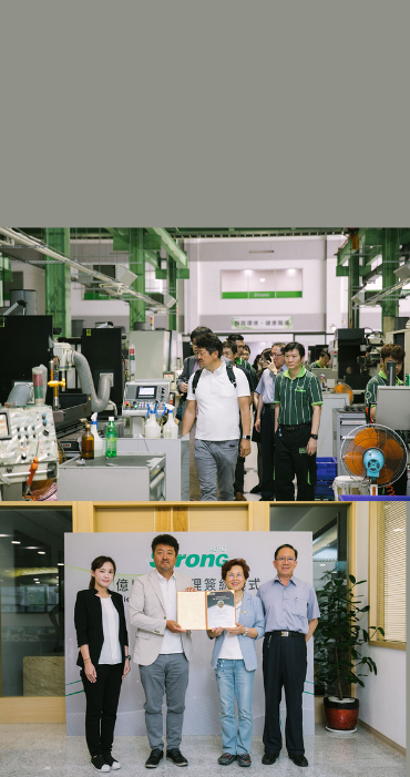
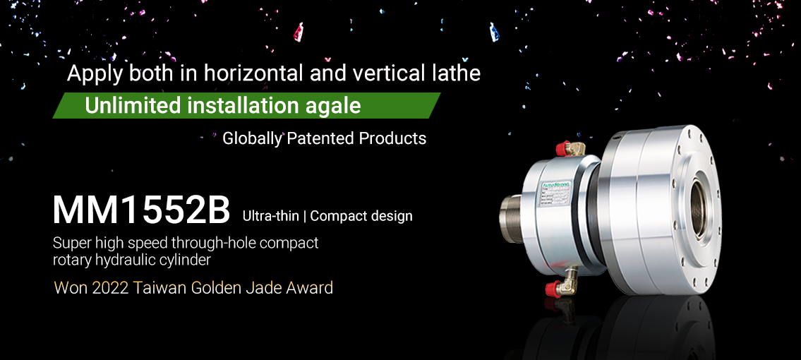
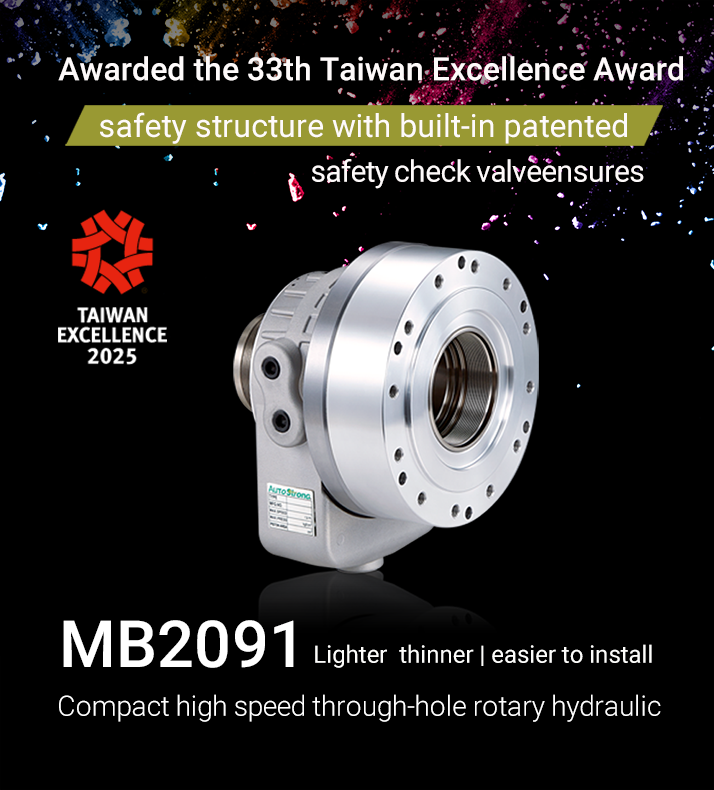
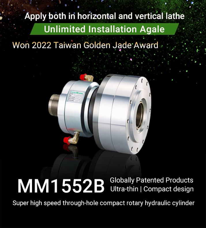
Under the brand “AutoStrong” Di Chun Iron Works has specialized in the manufacturing of power chucks, hydraulic cylinders, and collet chucks since 1974. earning the trust of wide range of customers and suppliers.
AUTO STRONG
FIFTY YEARS OF
RESOUNDING INTERNATIONAL
RESOUNDING INTERNATIONAL
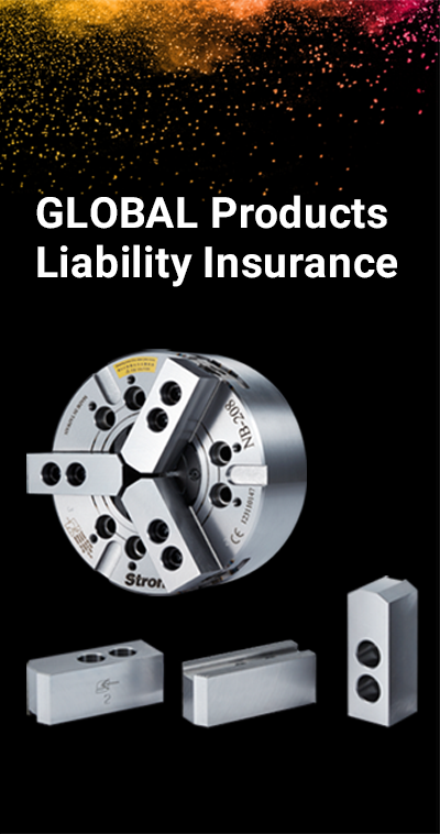
OUR RESPONSIBILITY

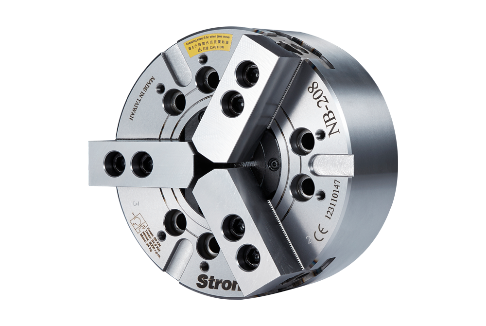
Large wedge type non through-hole power chuck
FCD600 Ductile Iron/ High Hardness, Hard to deform
For clamping huge workpiece Equipped with Protected cover on the gauge of chuck face, suitable for vertical lathe
Learn more >> 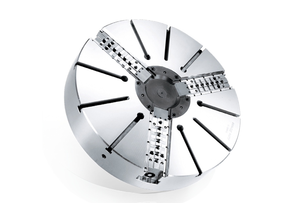
3-jaw extra large through-hole power chuck
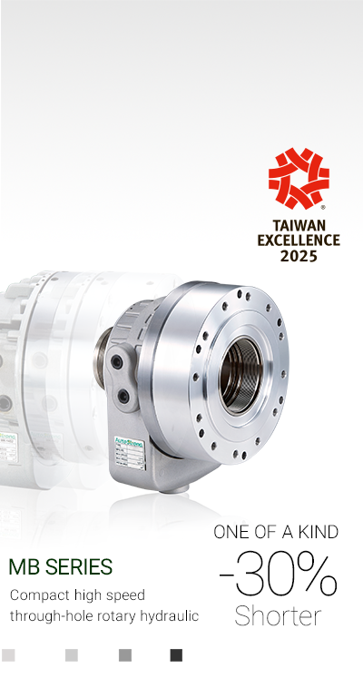
approximately 20% higher speed, higher gripping force and larger bore compared with regular chucks
Sliding surfaces, master jaws and interior parts are hardened treatment
Learn more >>